This project will involve using a little a bit of code and a very simple circuit that’s great for beginners.
The video further down this page will go through all the steps to completing this very cool DIY Wireless Notice Board project.
This project aims to control the LCD using wireless technology. This will serve as a base to build more amazing projects on home automation and many more automation projects.
The notice board is used to update peoples with new information or
If you want to send message with in room or in hall but are not want to talk loudly then this project will help you.
The project based on HC-05 Bluetooth module which Controlling16x2 LCD display.
You can turn on or off the LCD display via smartphone and also you can send the text message.
Working on Basics
The LCD have been powered by Arduino UNO (Board). It contains a code which uploaded to the board. And once it simulated you can connect with Bluetooth Module (HC-05) with you compatible device
Once code have been uploaded and Connected the Bluetooth and start Sending Command through app known as ArduinoBluetoothControl and start Sending Command you will be able to see that the desire Command which have been sent through app start's displaying on LCD.
Refer to this video there is full instruction how to Download and Use app and how to use app. CLICK HERE
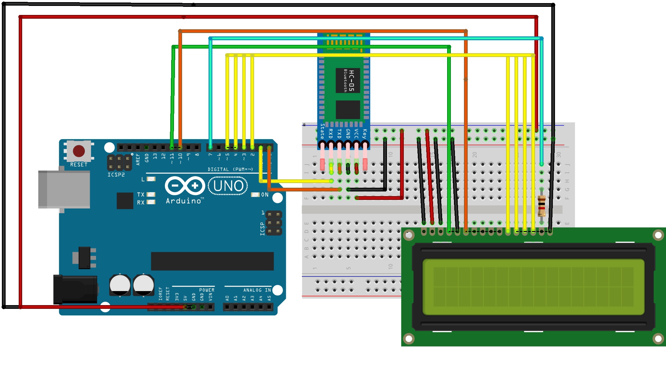
Connection of HC-05
Connection Of LCD
Uploading and Testing
Watch the Demonstration Video
Connection of HC-05
Hook the GND pin (Negative Pin) of HC-05 to Pin GND of Arduino.
Connect Red VCC Pin (Positive Pin) of HC-05to VCC of Arduino.
Connect TX pin (Data Transfer Pin) of HC-05to RX pin of Arduino.
Connect RX Pin of HC-05 to TX Pin of Arduino.
Connection Of LCD
Connect the First pin from the left of LCD (GND pin) with GND pin of Arduino.
Connect the Second pin from the left of LCD (VCC pin) with VCC pin of Arduino.
Connect the Third pin from the left of LCD (V0 pin) with GND pin of Arduino.
Connect the Fourth pin from the left of LCD (RS pin) with 11 pin of Arduino.
Connect the Fifth pin from the left of LCD (R/W pin) with GND pin of Arduino.
Connect the Sixth pin from the left of LCD (E pin) with 10 pin of Arduino.
Connect the Eleventh pin from the left of LCD (D4 pin) with 5 pin of Arduino.
Connect the Twelveth pin from the left of LCD (D5 pin) with 4 pin of Arduino.
Connect the Thirteen pin from the left of LCD (D6 pin) with 3 pin of Arduino.
Connect the Fourteenth pin from the left of LCD (D7 pin) with 2 pin of Arduino.
Connect the Fifteenth pin from the left of LCD (5V pin) with 1 K Resistor with 2 pin of Arduino.
Connect the Last pin from the left of LCD (GND pin) with GND pin of Arduino
#include /* * Idea By:- Devloper Krishna Agarwal (DIY Inventor) * Devloper Krishna Agarwal (DIY Inventor) * Desgign By:- Devloper Krishna Agarwal (DIY Inventor) */ char str[34],L=2; int draft=0,i=0; int Pass=0,p=0; int c,x,d; LiquidCrystal lcd(11,10,5,4,3,2); void setup() Serial.begin(9600); pinMode(7,OUTPUT); lcd.begin(16, 2); > void loop() if(draft==1) check(); draft=0; i=0; delay(1000); > > void serialEvent() while (Serial.available()) char inChar=Serial.read(); str[i++]=inChar; delay(10); > for (p=i+1;p34;p++) str[i++]=32; > draft=1; Serial.write(str); lcd.setCursor(0, 0); lcd.print(str); if(i>16) d=16; for (x=0;x17;x++) lcd.setCursor(x,2); lcd.print(str[d]); d++; > > > void check() if(!(strncmp(str,"1",1))) digitalWrite(7,50); lcd.clear(); > else if(!(strncmp(str,"2",1))) digitalWrite(7,LOW); lcd.clear(); > >
Hello Guys, My name is Krishna Agarwal , and I'm passionate about Making DIY Projects. Here I make Arduino and Robotics related projects.